


Rotary Spline
What is Rotary Spline
The rotary spline is a linear motion mechanism utilizing the recirculating motion of ball elements. It can be used in a wide variety of applications including robotics and transport type equipment.
Advantages of Rotary Spline
Increased load capacity
The rotary to linear mechanism of rotary spline can typically handle 10 times the load of conventional ball bushings, which only maintain a single point of contact at any given time.
Greater travel life
By utilizing the large ball contact surface of arch-shaped grooves, travel life is extended by up to 700 times (compared to conventional ball bushings).
Fewer number of parts
Similarly, by providing both linear and rotational motions, rotary spline effectively perform the work of two components. In addition to allowing for smaller devices, this also minimizes the number of parts required, which saves you money and reduces maintenance requirements.
Increased opportunities for miniaturization
Rotary spline feature a single-axis configuration that, when compared to the dual-axes system of most ball bushings, allows for smaller and lighter systems overall.
High Accuracy
Rotary spline provide exceptional accuracy in any application in which precision is a necessity.
Higher rigidity
The compact design of rotary splines doesn't come at the expense of rigidity, thanks to their four-row ball circuit structure.


Why Choose us
Reputation
A company with a positive reputation is more likely to attract customers. Reputation is built through consistent quality service or products, good customer relations, and reliability.
01
Customer service
The company offers excellent customer service and support, making it easy for customers to resolve any issues they may have with the product.
02
Quality assurance
We prioritize delivering high-quality services, and our output is subjected to quality checks to ensure that our clients receive the best possible services.
03
Competitive pricing
We offer competitive pricing on all our products without compromising on quality.
04
Innovative and unique products
We are always creating innovative and unique products to keep our customers interested and engaged.
05
Rotary Spline Applications in Manufacturing
Rotary spline shafts are frequently used in automobiles, aviation, and earth moving machinery as they can handle high rotation speeds to deliver torque. Unlike alternative shafts like key shafts, spline shafts can deliver more torque due to the even distribution of the load across all the teeth or grooves.
Many manufactured products include rotary spline such as bicycles, motorized vehicles, and more.
Many industries utilize rotary splines or products with splines such as, commercial, defense, general industry and equipment, energy, healthcare, musical instrument, leisure, power tool, transportation, and scientific research.
Methods of Machining Rotary Spline

Milling
Serrations and parallel or involute splines can be milled. A double angle milling cutter designed to produce the space of a serration or rotary spline is used to machine the spaces between the teeth. For involute splines, a milling cutter that has the reverse form of the involute for that specific diametral pitch, pressure angle, and number of teeth would be used to machine these spaces. The use of an index, dividing head, or CNC rotary table provides the index between teeth.

Hobbing
All types of external splines can be produced with the hobbing method. A cylindrical hob with the mating rack form of the rotary spline to be produced is the cutting tool. The number of starts of the hob and the number of teeth in the spline determine the ratio that the hobbing machine is geared or programmed to produce. The hob then “rolls” with the spline, as a gear would roll with a rack, while the hob traverses the work along the work axis of rotation. The cutting teeth of the hob remove material from the spaces between the spline teeth.

Shaping
This method can be used to produce both internal and external splines. A shaper cutter — a disc with a given number of teeth, diametral pitch, and pressure angle — has a cutting edge at one face. The ratio of the number of teeth in the cutter and the number of teeth in the work determine the differential gear train or programmed ratio for the shaping machine.This determines the specific rotational ratio between the cutter and work. The cutter is then reciprocated along a parallel axis to the work while both cutter and work are rotating. The cutter and work roll together (as a gear and pinion would) while the cutter removes material from the work during the down stroking action. The resulting teeth on the work have generated involute sides.
The benefits of splines
Parallel key spline - This type has equally spaced teeth that are straight sided. The teeth on the shaft have an equal tooth thickness at any point measured radially out from the axis of rotation. Conversely, the internal parallel spline has corresponding straight-sided spaces. This type of spline is similar to a keyway drive, with the exception that the keys are integral to the shaft and equally spaced around the circumference. The piloting feature can be the outside diameter of the shaft and major diameter of the internal spline or the inside diameter of the internal spline and the minor diameter of the shaft. Types of fit are 1) permanent; 2) to slide when not under load; 3) to slide when under load. Types of fits and tolerances are described in the SAE handbook.
Involute spline - Again, this type has equally spaced teeth, but they are not straight sided. The teeth have an involute form, just like a gear tooth. The teeth do not have the same proportions as a gear tooth; they are shorter in height. This truncated height combined with the involute form sides provides greater strength. There are no sharp inside corners at the base of the teeth as found in parallel key spline drives. Instead, there is a smooth transition through a fillet radius. This decreases the possibility of fatigue cracking in these areas. Involute splines come in several varieties: flat root side fit, fillet root side fit, and major diameter fit.
Crowned spline - These splines are typically involute. They can be flat root, fillet root, or major diameter fit. The purpose of this type of spline is to allow for angular misalignment between the shaft and mating detail. This is accomplished by “crowning” the male tooth. The tooth (usually) has a symmetrical crown about the centerline of the spline face-width. At this centerline, the tooth thickness is at its maximum. Moving toward the ends, the tooth thickness gradually decreases with the thinnest sections occurring at each end face. The tooth thickness is measured at the pitch diameter. Usually the outside diameter of the spline is also crowned, with the largest diameter occurring at the same location as the thickest tooth thickness, and decreasing proportionally to the designed misalignment toward each end face. The female spline is usually not crowned.
Serration - This type of spline has a tooth form that is non-involute. The teeth of the male detail are in the form of an included angle with the female serration having spaces of the same included angle. Serrations are generally used on smaller diameter drives where an involute form would not add strength. Because the teeth are a simple included-angle form, more teeth can be used on a small circumference providing a greater contact area. Serrations are used in instrument drives, valve shafts, and the like. Standards are found in SAE, JIS, and DIN.
Rotary spline - These can be either parallel or involute tooth form. The rotary spline has a specific lead and helix angle. These splines are used for several applications.
Rotary Spline Inspection
Gage pin measurements
One, two, or three-gage pins of a specific diameter placed in the spaces of the rotary spline can be used to obtain a measurement over or between pins. A gage pin of a specific size will contact the involute sides of the spline teeth. The calculated dimension for the over or under pin measurement, depending upon whether it is an external or internal spline, determines the actual tooth thickness or space width. This actual measurement of the tooth or space width does not take into account any other elements of a spline. Because of this, the actual thickness or space-width tolerance band begins at the minimum material condition to ensure fit between details.
Composite
Composite go and no-go gage sets check the spline to the effective tooth or space width. The effective fit is one that is “tighter” than the actual fit measured by the pin method. The effective fit is intolerant of spacing, involute, or lead error. Both go and no-go gages are made with a full complement of teeth. The gages are “perfect” in all elements: spacing, lead, and involute. Splines machined to these standards are machined to the effective tooth and space widths. This tolerance band is taken from the maximum material condition and will slightly overlap the actual tooth thickness dimension. It is possible to produce a spline that “takes” the go gage but is still out of tolerance to the actual tooth or space width as measured over or between pins. This is an acceptable condition as the go gage ensures a fit with the mating part.
Sector no-go
Use of this gage allows the whole range of tooth thickness tolerance, from minimum or maximum effective to minimum or maximum actual tooth or space width. In this case a full composite go gage and a sector no-go gage would be used.The sector no-go gage has two groups of two or more diametrically opposite teeth. These teeth (or spaces on a ring gage) are produced to the maximum actual space width (plug) or minimum actual tooth thickness (ring) part allowance.
How to specify a Rotary Spline
Importance of preload
When a force causes rotation of either the shaft or the spline nut (not the radial support bearing), the two will rotate together because the nut’s ball bearings are secured by the grooves.If the ball bearings aren’t preloaded, there can be some wiggle room between the spline nut and the shaft. So, when you want to move a load by rotating the shaft, the nut doesn’t immediately follow or it moves over a little due to the slight clearance. That is angular backlash, and it’s detrimental to accurate positioning.Of course, there is a trade-off. The higher the preload, the tighter the balls are in the grooves and the more friction is produced. Thus, it’s important to select the appropriate preload for the application to maintain smooth movement and to maximize product life, rigidity and accuracy.
Maximizing torque
The torque rating of a rotary spline is determined by the number of grooves on the shaft and the number of points of ball contact in the grooves. Shafts with four grooves will have higher torque ratings than those with three grooves.Likewise, grooves shaped like gothic arches, which provide four points of ball contact, have higher torque ratings than circular grooves, which provide two points of ball contact. The Gothic arch design eliminates any clearance that could lead to deflection. This makes the ball spline more precise. Four-point contact also increases load capacity and rigidity.Though different ball splines might be exactly the same size, they can have different torque ratings based on the total number of contact points between the shaft and the spline nut. A ball spline with four grooves and four-point ball contact provides 16 total contact points between the shaft and the spline nut. A ball spline with three grooves and two-point ball contact provides just six contact points between the shaft and nut.
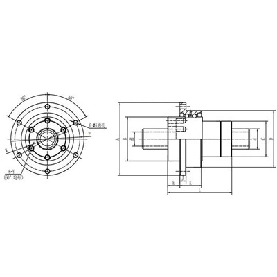
Shaft characteristics
Spline shafts can be drawn, ground or precision-ground. The base material can also vary. Shafts are ranked according to such characteristics as material grade, shaft diameter tolerance, perpendicularity to the end face, and concentricity of the part-mounting section in relation to the support section.Increasing the symmetry of the spline shaft will increase its maximum rotational speed and stability.Machining precise, straight linear grooves on a spline shaft will make it highly accurate, but also more expensive. Drawn spline shafts are less expensive, but also less accurate.
Material of Rotary Spline

Alloy steels
Alloy steels are ferrous alloys based on iron, carbon, and alloying elements such as chromium, molybdenum, vanadium, and nickel. Alloy steels include hardenable high-alloy steels, high-strength low-alloy steels, maraging steels, and other specialty steel alloys.

Aluminum alloys
Aluminum alloys provide high toughness at moderate strength levels, with good corrosion resistance and less-than-half the density of steel.

Carbon steel
Carbon steel is a commercial iron that contains carbon in any amount up to about 1.7 percent as an essential alloying constituent. It is malleable under suitable conditions and distinguished from cast iron by its malleability and lower carbon content.

Stainless steels
Stainless steels are highly corrosion resistant, ferrous alloys that contain chromium and/or nickel additions.
Our factory
Wenzhou Xionglian Hardware Machinery Co., Ltd. is a member of China Machinery General Parts Industry Association. The company was founded in 1988, is a modern manufacturer integrating production, R&D, manufacturing and sales. The company focuses on the production of fasteners, stamping parts and special kinds of fasteners. Our products are widely used in machinery, automobile, military, aerospace, metallurgy, mining, industrial automation and others.


Our Certificate


Asked Question
Q: What is the purpose of a spline?
Q: What's the difference between gear and spline?
Q: What is the difference between a ball screw and a Ball Spline?
Q: What is the purpose of splined shaft?
Q: What are the advantages of splines?
Q: What do you strengthen with a spline?
Q: What is the pressure angle of a spline?
Q: What is a spline and how does it work?
Q: What is the disadvantage of a ball screw?
Q: Which is better ball screw or lead screw?
Q: Why is it called a spline?
Q: How do you spec a spline?
Q: Do splines add strength?
Q: Do splines have backlash?
Q: How deep should a spline be?
Q: How long does spline last?
Q: Can you reuse old spline?
Q: How many knots for spline?
Q: What is the pitch diameter of a spline?
Q: What is a knot in spline?